|
|
Kitfox™
SERVICE LETTER #25
March
12, 1993
SUBJECT:
Lift Strut Attachment
TO:
Kitfox™ Owners, All Models
FROM:
SkyStar Aircraft Corporation
Recent
experience with creation of the Kitfox™ XL manual has allowed us
to rethink the way we answer two commonly asked questions:
1.
How do I make sure my dihedral is set correctly?
2.
What should I do if I find a need to force (lift with
pressure) the forward or aft lift strut, to make
DIHEDRAL
The
first question, regarding dihedral, is easy to answer through the
use of a 4 ft. carpenter’s level. Your first step is to follow
the existing directions by positioning the Lift Strut Bracket onto
the spars, so that the center of the Strut Bracket bolt hole is
96.75 inches from the root end of the spar for Model IV and XL
aircraft. For the Speedster, use an initial starting point of
97.75 inches from the root end of the spar. The Lift Strut
Brackets should be temporarily held in place with hose clamps.
Follow existing instructions for temporarily installing both
wings, making sure you DO NOT drill the rear spar bottom
hole, or either top or bottom front spar holes, until a final
dihedral check is made.
The
final dihedral check is made only after making sure the fuselage
is leveled both laterally and longitudinally. Once the fuselage is
leveled, with the wings, struts and Lift Strut Brackets
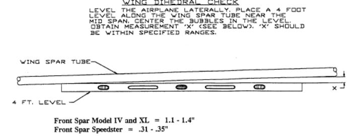
temporarily assembled, simply hold your 4 ft. carpenter’s level
up to the bottom of the leading edge spar at a mid span location.
Because of the dihedral, the bubble will not be centered if the
level is held firmly against the spar. Simply lower the “wing
tip” end of the level until the bubble is centered. The
following distance should exist between the “wing tip” end of
the level and the spar:
|
|
You
can further increase dihedral accuracy by also checking the rear
spar. After checking the front spar, simply multiply the value you
measured (let’s say it was 1.1”) by 1.137. In this example,
1.1” x 1.137” =
1.25”, meaning the
top edge of your 4 ft. level should be 1.25”
below the rear
spar.
If
these distances are not present, simply loosen the clamps holding
the Lift Strut Bracket and move the brackets inboard to increase
dihedral, or outboard to decrease dihedral. Once you are satisfied
with overall wing alignment, complete the wing installation, as
indicated in your Builders Manual.
STRUT
FIT
In
some cases, a gremlin called “weld warp” causes carefully
jigged, welded parts to fit incorrectly when installed on an
airframe. This “warping” results from unevenly heated surfaces
acting upon surrounding metal in a fashion which distorts the
intended shape. Fortunately, the flexibility of 4130 steel tubing
permits such warping to be resolved, in many cases, by applying
pressure on the part, to rectify the warped condition. The elevator
to stabilizer fit is often subject to such warpage, and requires the
builder to “nudge” parts until a pleasant fit is obtained.
Recently,
we have seen some wing lift struts exhibit an alignment issue
wherein, after attaching the forward strut to the front spar attach
bracket, the rear strut hangs below the rear spar attach bracket. In
some cases, a good deal of force must be applied to move the rear
strut into place. Can anything be done about this
you bet!
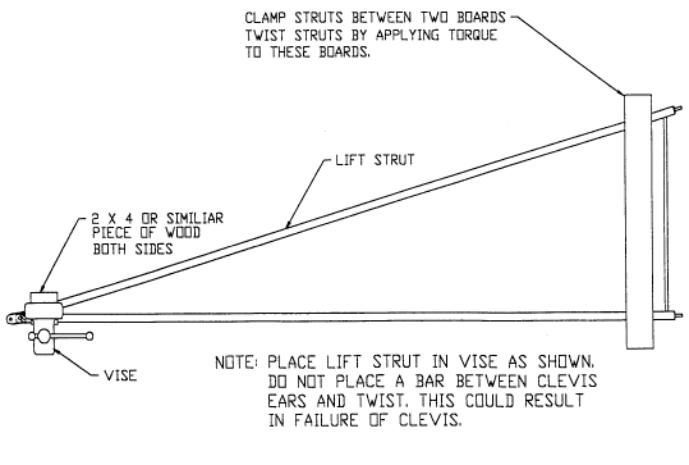
By clamping the “fuselage” end of the strut into a vise (with boards on each side to prevent scoring), a twisting force can be applied to the “wing” end of the struts, thereby correcting the misalignment. The diagram below shows the proper placement of clamps and force. The strut must be nudged past the actual point of adjustment required to allow for the natural spring back. This process may be repeated several times until a tension free fit is secured. Absolutely no harm is caused to the struts, and you will have ensured a custom fit to your specific wing dimensions. Please feel free to contact Builder Support if you have any questions.