|
|
December 15, 1992
SERVICE
BULLETIN #29
SUBJECT:
HEADER TANK AND FUEL LINE ROUTING FOLLOW-UP
(Follow-up
to Service letter #22) MANDATORY
TO:
ALL Kitfox™ BUILDERS WITH HEADER TANKS
FROM:
SKYSTAR AIRCRAFT
Service
Letter #22 was an advisory
to all Kitfox™ owners who utilize a header tank in conjunction with
one or more wing tanks. It dealt with the possibility of fuel not
flowing to the header tank from the wing tank if the wing tank fuel
pick up is un-ported, causing air to enter the line. Then fuel flow
stoppage to the header tank, can cause the header tank to drain;
resulting in fuel starvation to the engine.
This
Service Bulletin will deal with specific recommendations and
instructions on how to deal with this potential problem. The overall
object, is to have the fuel flow from the wing tank to a rear mount
header tank and then forward, to the firewall with the greatest amount
of droppage as possible (gravity feed with no high point) . It has
also been determined that deleting the individual fuel valves
from each wing tank, helps prevent, air entrapment in the fuel lines.
RECOMMENDATIONS
(1)
: All front mount header tank systems must be removed and a rear mount
header tank must be installed. (SkyStar Aircraft is offering a new,
rotationally molded header tank for easier installation of a retrofit
rear mounting position, at a special reduced price for this Bulletin.)
(2)
: Each wing tank fuel valve must be removed from the headrack.
(3)
: The fuel line routing, should flow directly from the wing tank to a
rear mounted header tank. From the header tank, fuel line routing
should travel down to the bottom of the door frame, forward (under the
door frame) to the firewall, across the firewall to the shut-off
valve.
NOTE:
For those operating wing tanks in conjunction with the large, front
main tank, the wing tank fuel lines should route:
forward
from the wing tank, above the door frame work, down the diagonal
bracing in the windshield area, and plumbed directly into the filler
neck of the main tank. The wing tank fuel valve can be
|
|
installed
in the headrack above the door. Because of the capacity and fuel
visibility in the main tank, the question of fuel flow stoppage from
the wing tanks is not as critical. With the fuel routed into the
filler neck, you will have a constant visual on all fuel.
Enclosed,
you will find in-depth instructions for the mounting and retro-fit
mounting of the rear mounted header tank. You will note that some of
these instructions are in the form of revised manual pages. Those who
have the new format construction manual should exchange these pages
for those in their manual. The new pages are marked “Revision” 1.
If
you have questions regarding this Bulletin or procedures, please feel
free to call our Technical Support Department. The Header Tank
Replacement Kit, front mount to rear mounted header tank, is part
number #69141 and will normally retail for $119.99. Those ordering in
response to this Bulletin will be able to purchase this kit (#69141)
for the price of $76.00. Those aircraft which presently utilize a rear
mounted header tank, may use there existing header tank but need to
modify the routing, extra #47000 Fuel Line for this modification and
the Replacement Kit can be ordered from the Customer Service
Department. Phone: (208) 466-1711 Fax: (208) 466-7194
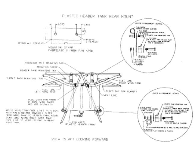
Rear
Mount Header Tank (#44071) Installation
Preface
Read
each step carefully to determine the specific application to your
installation. Some steps may not, in there entirety, deal with your
application; but, may contain points that you should be aware of and
act upon.
1.
Drain all fuel from the wing tanks and header tank. Try
2.
Remove baggage sack and seat back cover.
3.
Remove the existing fuel line and #29001 Wing Tank Fuel Shut Of
f Valve from each wing tank to the front rear mounted header tank.
(For existing Rear Mount Modification, skip to Step 9.)
4.
Remove the existing aluminum #65032 Front Header Tank from the
firewall bulkhead.
5.
Attach the #44071 Header Tank (new rotationally molded) to
fuselage diagonal brace tubing, above and behind the control system.
as per Fig CFO-4b.
6.
Install #94002 Elbow Fittings in the #44071 Header Tank inlets
and outlet. For single wing tank aircraft us a #94005 Plastic Plug in
place of the #94002 Elbow. Use a good grade thread sealant on all
threads. Be sure to use a wrench on the hex portion of the brass
adapter bushing, to prevent its turning when tightening the Elbow.
Orient the barbed, inlet Elbows outboard and outlet Elbow to the left.
Also install a #94000 Vent Elbow using above procedure and orient the
barbed end to the right. See Fig. CFO-4b.
7.
Install the #44000 Rubber Fuel Line Hose between the Wing Tank
Outlet and the Header tank. Route the fuel lines to insure a
continuous drop, from the Wing Tank to the Header Tank. Secure these
lines to the fuselage structure with tie wraps. Make sure the Hose is
long enough to allow folding of the wings. Route the Hose under the
headrack carry through brace as shown in Fig WO-3-l. (For those with
an existing, Aluminum Rear Mount Header Tank, slip the hose over the
inlet nipple and secure with a hose clamp.)
8.
If not previously accomplished, install a return vent
NOTE:
All aluminum fuel lines should have a 370
flare,
mating up with its respective fitting.
10.
Recalculate the Empty Weight C.G. using following information :
COMPUTING
NEW CG
ITEM
MAKE & MODEL
WEIGHT
X
ARM
=
MOMENT
Extreme
AFT CG
Rear
Header Added
7.9
45.9
362.61
Added
Front
Header Removed
-7.5
-15.5
116.25
Removed
NEW TOTALS